Hack the "Arduino Robot" is a new challenge category at RobotChallenge 2014 sponsored by RS Components. For this section 10 "Arduino Robots" were given to 10 teams/individuals selected by a jury to be used in their projects.
My plan is to use "Arduino Robot" as the core of a sorting system for used batteries. The system will accept batteries of the following types: AA, AAA, C, D and 9 Volt.
The batteries inserted in the sorting system will be divided in two categories:
- AA and AAA will be used to charge a backup battery, charge the robot itself or provide power for an emergency charger through an USB port. When they are empty will be dumped in a battery recycle bin.
- the other types of batteries will be sent directly to battery recycle bin.
"Arduino Robot" is designed by Arduino and Complubot as a solution for a mobile robotic platform equipped with 2 ATmega32u4 controllers, TFT screen, motor driver for two motors, compass, keyboard, charger for 4 NiMh cells. These components are distributed on two boards:
- Control board - 1 x ATmega32u4, color TFT screen, compass, buzzer, potentiometer, 5 keys keyboard and input/output pins.
In/out pins are named from TK0 to TK7 (M0 to M7 on my board) and TKD0 to TKD5 (D0 to D5 on my board).
Pins from TKD0 to TKD5 are connected directly to ATmega controller and can be used as INPUT or OUTPUT pins.
Pins from TK0 to TK7 are conected to a multiplexer and can be used ONLY as INPUT pins. These 8 pins can be very useful when a large number of sensors is used. Also, BCHARGE and BON are brought in the multiplexer, these pins can be used to check if the charger is connected to robot and if the NiMh cells are charging. Possibility to access pins from TK0 to TK7 came with the cost of 5 pins, two of them are TKD4 and TKD5 and the other three are directly connected from controller to multiplexer (ATmega pins D4, D11 and D13).
Than means, when use pins TK0 to TK7, pins TKD4 and TKD5 cannot be used. See table below for Control Board pins.
Also Robot.analogWrite() works ONLY on TKD4 and it cannot be used at the same time with TK0 to TK7.

I wrote a little about I/O pins because I need to connect a number of sensors and servos to AR.
An other thing I need to use in my project are servos. Servos are very useful because you can move/rotate things without additional circuitry, you need only one controller pin per servo. To make things easier some fine people write a servo library for Arduino, making the use of servos an easy process.
Unfortunately you cannot easily include "Servo.h" library (at least for now) because it interfere with Melody.cpp used by "ArduinoRobot.h".
My solution was to simply delete/move Melody.cpp from its original place. Of course functions related to Melody.cpp will not work anymore but for my project they were not important.
To draw a conclusion, "Arduino Robot" have many built in components and ready made functions to help in developing a mobile platform and in generally to build applications using Arduino ecosystem. There are a couple of interesting undocumented functions like BCHARGE, BON, motors current sensing and maybe others I did not find, but I'm sure they will be covered by the developers and community.
One thing I would like "Arduino Robot" to have, is the possibility to choose if you want to use onboard potentiometer, buzzer, keyboard, MUX or you want to use controller pins for something else. I think it will be useful to have the possibility to select/deselect them with jumpers or DIP switches.
"Hack the Arduino Robot" - The battery sorting project
The project I proposed for "Hack the Arduino Robot" is a battery sorting system which takes used batteries at input, sort them by size - C,D and 9V size in one category, AA and AAA in other category.
Some time ago, I tested about one hundred batteries from a battery recycle bin and I found that more than two thirds still have energy left. Inspired by the Joule Thief devices, I used a step-up regulator and about 6-7 used batteries I could power various small devices. So I go one step further and I think do build an automatic system to extract this energy before throw batteries away for good. Let's see how it works:
- AA and AAA are sent to a transport arm which will store them in series of seven batteries. The remaining energy is then extracted using a booster regulator with 5V output. After complete depletion they are dumped to a recycle bin.
- C,D and 9V size are dumped directly to recycle bin.
The system have three main components - ArduinoRobot, battery selector and transport and storage arm.
Pictured below is the schematic of the battery selector and its working diagram.

The selector is organised in 3 steps:
- step 1 - if a larger battery size is introduced trough the input slot, they are stopped under "Sensor 1". If Sensor1 detect an object for more than 3 seconds, "Hatch 1" is opened and batteries stopped there are released to recycle bin.
- step 2 - if a AA battery is introduced, it goes until reach the lower ceiling at "Sensor 2". If Sensor2 detect an object for more than 3 seconds then measurement process is triggered.
If battery is found to have more than 1V, the "Mobile hatch" is raised and the battery is dropped to the transport arm to be carried to storing tubes (more on that later).
If battery have less than 1V, "Hatch 2" is opened and battery is released to recycle bin.
- step 3 - if a AAA battery is introduced, it goes until reach the wall at "Sensor 3". If Sensor3 detect an object for more than 3 seconds then measurement process is triggered.
If battery is found to have more than 1V, the "Mobile hatch" is raised and the battery is dropped to the transport arm to be carried to storing tubes (more on that later).
If battery have less than 1V, "Hatch 2" is opened and battery is released to recycle bin.
In order to reduce the mechanical complexity of selector mechanism, the batteries will be introduced in a predefined way, with "+" to left for ex.
In order to have their voltage added, batteries which passed measurement test are transported and stored in four tubes - two for AA and two for AAA. This is achieved with the help of a motorized arm.
Transport arm is made from an aluminium square tube. At one end is mounted on an axle which allow a circular movement. Movement is generated by a servo modified for continuous rotation and is controlled by AR motor driver.
The arm position is determined with the IR sensors mounted under MotorBoard. Sensor 0 is the home position, sensors from 1 to 4 correspond to battery storage tubes. The value of these sensors is read with commands Robot.updateIR() and Robot.IRarray[x] where "x"is the sensor number. Robot.IRarray[x] return an analogue value.
I hope pictures and the short video below will explain better how it looks ans works.


And here is a short movie with the first battery drop - https://www.youtube.com/watch?v=-XUHK6UG-Mw
The storage tubes have electrical connections at bottom and top. When a tube is filled with batteries, circuit is closed and the tube power a Step Up/Step Down regulator - like this one. Voltage generated at regulator output is used to charge a Li-Ion backup battery, power LEDs, etc.
Some construction pictures.
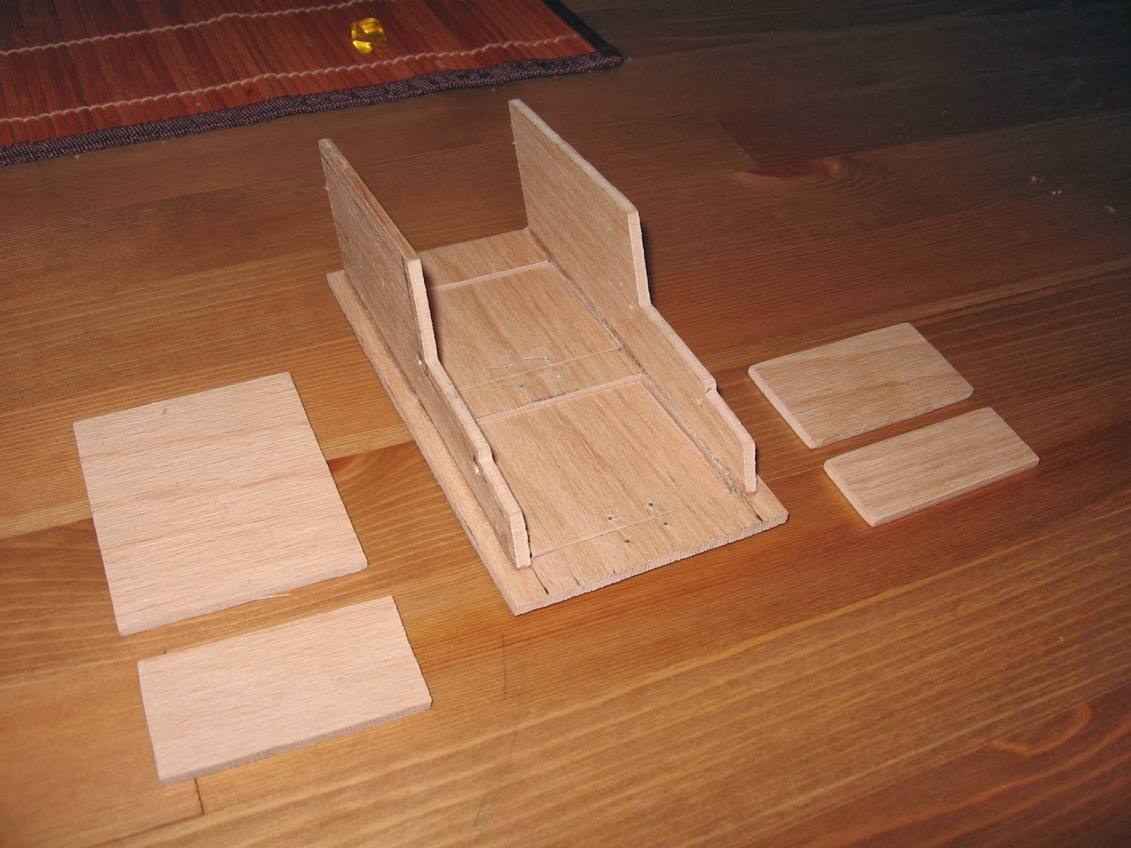

This is not a new Batmobile prototype, is the first construction stage of battery selector. This part took a LOT of work and tuning, mainly because the sensors I choose (TCRT5000) are very light and range sensitive. I found that their working range is between 5mm and 20mm, no less, no more. I even had to shoot videos showing robot in action in low light because of sensors sensitivity.
TCRT5000 connections schematic:

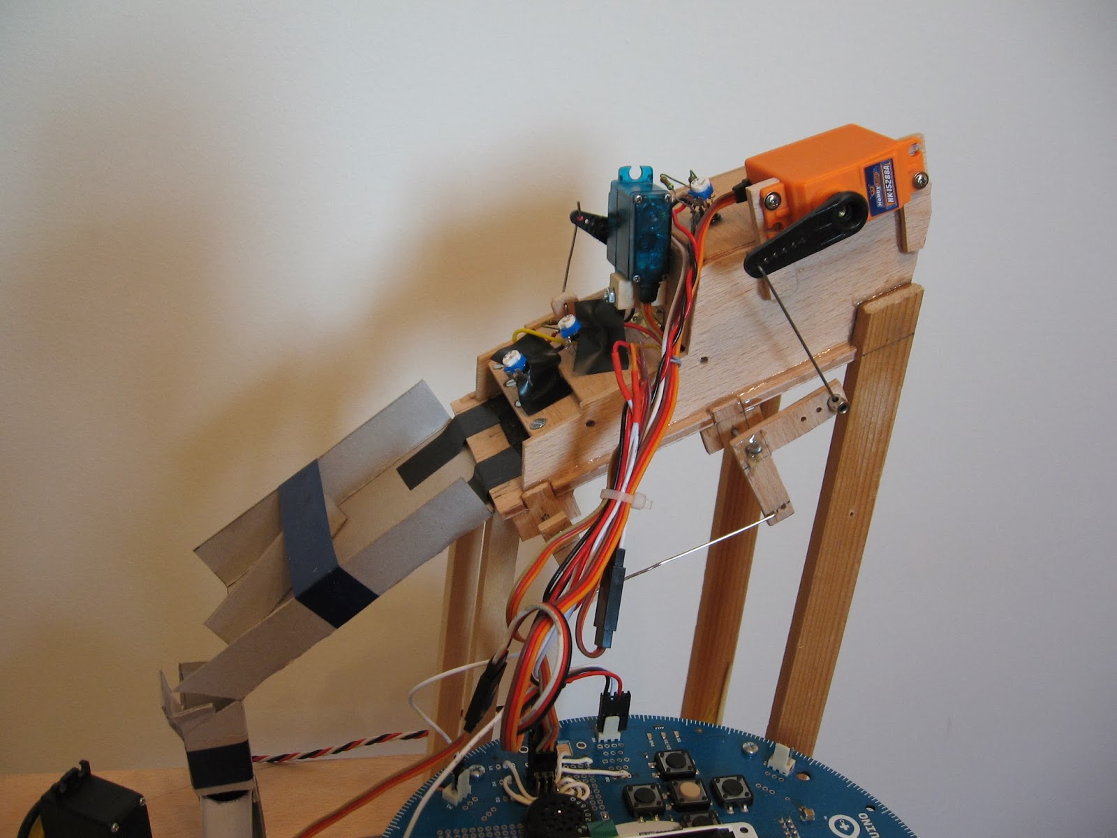
And some pictures with the finished unit, ready to be mounted.


Mounted and connected to Arduino Robot:

After batteries from tubes are depleted and/or new batteries are introduced, the storage tubes need to be empty. For this, at the bottom of each tube is a tilting lid. These lids are kept closed with a servo.
This servo have two functions:
- first is to slightly open the bottom lids - in this way when a tube is filled with batteries, the mechanical tension created by the springs mounted on top and bottom lids is greatly lowered and the top hatch can be easily open and closed by transport arm.
- second is to completely release the bottom lids and allow batteries to be dumped to recycle bin.
Here you can see how this part looks:


Ok, but what about lead weights and aluminium tube. Lead weights are used to bring the bottom lids to horizontal position after batteries were released out of the tubes.
Aluminium tube is used to prevent that both tubes to be emptied at same time. Aluminium tube is mounted on same axle and pointing in same direction as transport arm. When transport arm is above tube one, the lower arm is above the first lid. In this way when servo open the lock for lids, only the lid of tube two is tilted and the tube is emptied, the lid of tube one been blocked.
Here you can see how everything is working - Battery Robot.
Arduino code - https://github.com/sebathorus/Hack-The-Arduino-Robot
Niciun comentariu:
Trimiteți un comentariu